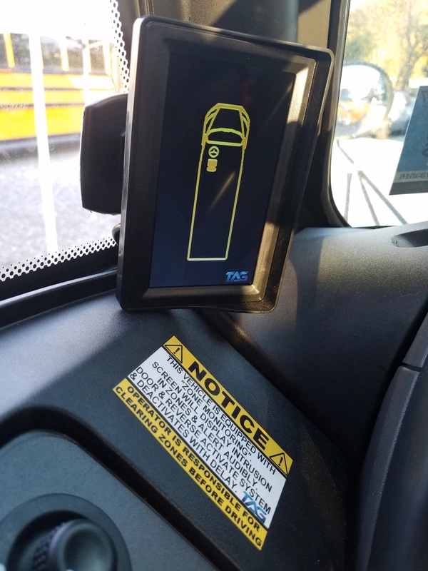
Display does not turn on
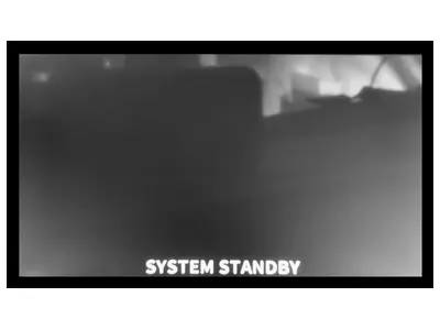
V3.0 may need a software update in some cases. Confirm ignition power, fuse, ground, and wiring connections. When ignition is on, the display should show an active camera or standby screen. Try the reset procedure below before replacing parts.
Display does not shut off
Try the system reset, then power cycle the controller by disconnecting power, ground, and accessory wires for 60 seconds. A failed or faulty microSD card can also lock the system while it tries to read or write recording media.
MicroSD missing, format, or recording media message
Verify a card is inserted and seated. Remove and clean the contacts with isopropyl alcohol or electronics cleaner. Formatting media can erase video, so only format when that is the intended service step.
Camera image is distorted, green, gray, or squiggly
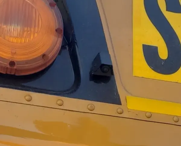
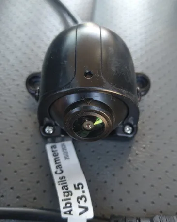
The controller may be programmed for the wrong camera type. V3.0 controllers function with V3.0 cameras. If a camera or controller was just replaced, confirm the correct camera type before continuing.
Front view does not display when the door opens
If the screen shows DOOR OPEN - FRONT VIEW, swap the front and rear threaded camera connectors to help isolate the camera or harness. If that text does not appear, check the door signal wiring. On passenger-vehicle platforms, confirm the dome light is in normal operating position.
Rear view does not display in reverse
If the screen shows REVERSE ACTIVE - REAR VIEW, swap the camera connections to isolate the camera or harness. If the status text does not appear, verify the reverse signal wiring and perform a system reset.
Display turns on during reverse and shuts off, or behaves inconsistently
The power and accessory wires may have been swapped. Verify wiring, perform a quick reset, then power cycle the controller for 60 seconds if the issue continues.
V3+ reset procedure
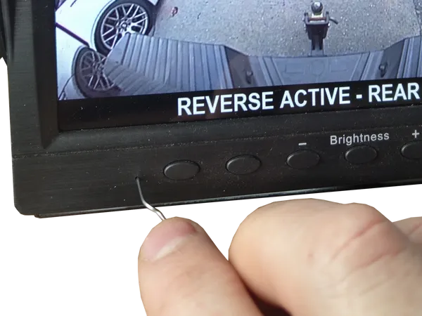
Insert a paperclip into the small reset hole on the lower-left front of the display. Press the internal button for at least 10 seconds, then release and allow the system to reboot. Do not insert into the hole on the right side; that may be the display microphone on recording-enabled systems.
V3+ wiring reference
Blue Reverse trigger, 12V positive from reverse activation
Green Door trigger, 12V positive
Purple Door trigger, 12V negative
Red Ignition signal, 12V positive
Yellow Constant battery power, 12V positive
Black Ground, 12V negative
Grey Alarm input from connected 12V positive source
Cameras Front/rear for Abigail's; AUX1/AUX2 for optional recording inputs

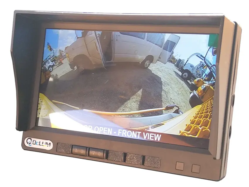
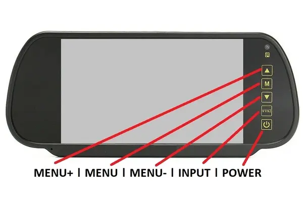
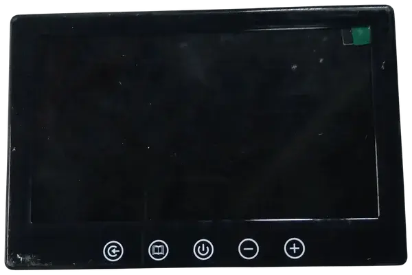
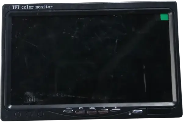 Display style
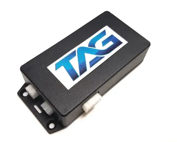
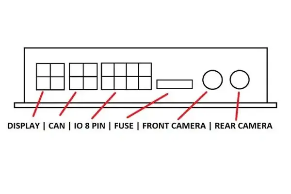 Controller and ports
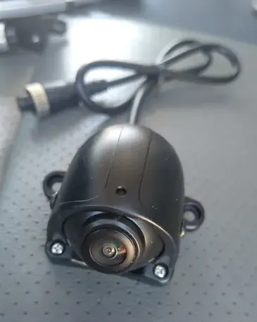 Camera connectors